Computed Tomography, the only non-destructive technology to see inside your samples!
Foundry components require many controls and inspections during the overall production process. Computed tomography (CT) is a powerful non-destructive technology to inspect every samples in an easy way and the only one giving the ability to see inside the matter.
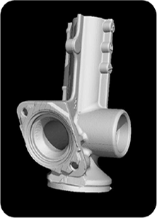
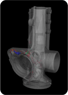
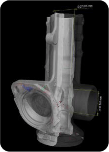
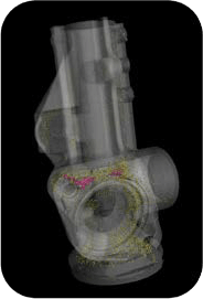
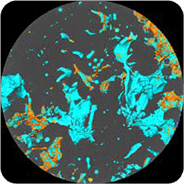
Automotive component scanned by RX Solutions showing a porosity analysis and dimensional measurements. Colors underline the different sizes of each porosity. Voxel size: 127 μm.
Computed tomography: Exploring foundry components
Foundry components are diverse and widely used in various industrial fields such as the automotive or naval industries. They have complex material behavior displaying a range of failure modes.
Industrial CT scanning technology is the only inspection technique able to characterize in an easy way the overall material structure of a foundry component. CT scan provide precise measurements of the overall sample, from the whole structure down to individual porosity level. Every structural and dimensional aspect of casting parts can be assessed through one CT dataset.
Structural analyses: Casting products validation
Industrial CT scanning allows quick and accurate inspection of parts’ internal and external structures. With a resolution up to 5 μm, RX Solutions CT devices enable the validation of tiny details on casting components. It is possible to define and export an accurate 3D model of the sample to make measurements of the inner and outer geometries, on simple or multi-material parts.
In the field of industrial research, nano inspection is widely used, to observe and characterise foundry components. Understanding the microstructure role helps to prevent cracks that can propagate through the intermetallic phases.
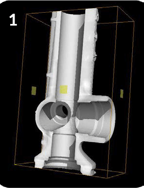
- Half 3D rendering of an automotive component using a 4 clipping box.
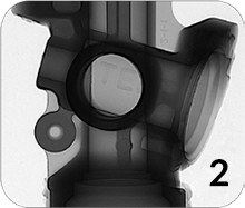
- Dradioscopyofacastingcomponent.Defects localization is very quick and simple.
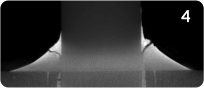
- Welding analysis on a casting component showing interruption of material cohesion (cracks).
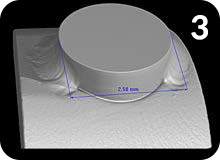
- 3D rendering of a welding with dimensional measurements.
Many different types of analyses can be performed using CT
CT datasets contain the entire sample geometric information and can be used to perform different kinds of analyses: voids analysis, actual parts to CAD comparison, part to part comparison, wall thickness analysis or reverse engineering.
Structural analyses: Welding analyses, CAD vs CT comparison
A large number of casting components contains a lot of welds and these connections must be perfect. Many times, a lack of fusion (LOF) along the weld leads to an interruption of material cohesion. Welds have to withstand high mechanical and thermal constraints, and a LOF can bring failures during the component utilization. CT and particularly the laminography mode is the best technique to easily and quickly inspect many welds.
Furthermore, a comparison between a CT dataset and a CAD nominal file can be made easily, to quickly and accurately compare the part to a CAD model, by showing the internal fibers deviations.
Defects analysis: Cracks, porosities, inclusions
Industrial CT scanning technology allows the identification of cracks, porosities or inclusions inside the scanned part. The volume fraction of pores and their spatial distribution in the sample can be calculated and highlighted with different colors using post-processing software.
RX Solutions CT scanners: Ease of use and automation
RX Solutions provides a software plugin called “CT wizard”: it makes RX Solutions DeskTom system very easy to operate, by adjusting automatically all CT settings. In addition, in a production line environment, an automation mode will dramatically reduce the cycle time for the control by setting all CT scan parameters automatically.